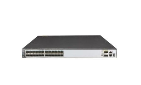


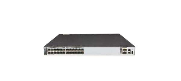
S6720-30C-EI-24S-AC
Version Mapping
Table 4-130 lists the mapping between the S6720-30C-EI-24S-AC chassis and software versions.
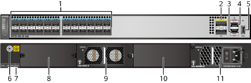
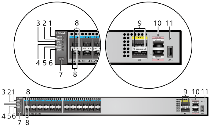
Appearance and Structure
|
1 |
Twenty-four 10GE SFP+ ports Applicable modules and cables:
|
2 |
Two 40GE QSFP+ ports Applicable modules and cables:
NOTE:
A 40GE QSFP+ optical port can be split into four 10GE ports. |
|
3 |
One ETH management port |
4 |
One console port |
|
5 |
One USB port |
6 |
Ground screw NOTE:
It is used with a ground cable.
|
|
7 |
ESN label NOTE:
You can draw it out to view the ESN and MAC address of the switch. |
8 |
Rear card slot NOTE:
Card supported:
|
|
9 |
Fan slot NOTE:
Applicable fan module: |
10 |
Power module slot 2 NOTE:
Applicable power modules:
|
|
11 |
Power module slot 1 NOTE:
Applicable power modules:
|
– |
– |
Port Description
10GE SFP+ port
40GE QSFP+ port
Console port
ETH management port
|
Attribute |
Description |
|---|---|
|
Connector type |
RJ45 |
|
Standards compliance |
IEEE802.3 |
|
Working mode |
10/100 Mbit/s auto-sensing |
|
Maximum transmission distance |
100 m |
In V200R012C00 and later versions, you can log in to the switch that contains the ETH management port for the first time through the ETH port. For details, see “First Login to a Switch” in the Configuration Guide – Basic Configuration. If you have logged in to the device for the first time by pressing and holding the MODE button for 6 seconds or longer and saved the configuration, the default configuration on the ETH port will be cleared. In this case, you cannot log in to the switch for the first time through the ETH port. You are advised to log in to the switch for the first time through the ETH port.
USB port

USB flash drives from different vendors differ in model compatibility and drivers. If a USB flash drive cannot be used, try to replace it with another one from a mainstream vendor. Switches support a maximum of 128 GB USB flash drives.
Indicator Description
- If the switch has no configuration file, the system attempts to enter the web initial login mode. In this mode, the status of mode indicators is as follows:
- If the system enters the web initial login mode successfully, all mode indicators turn green and stay on for a maximum of 10 minutes.
- If the system fails to enter the initial login mode, all mode indicators fast blink for 10 seconds and then restore the default status.
- If the switch has a configuration file, the system cannot enter the web initial login mode. In this case, all mode indicators fast blink for 10s, and then return to the default states.
The S6720-EI series switches provide a command for setting fault indicators, which help field maintenance personnel find a faulty switch quickly.
The SYS indicator and mode indicators (STAT, SPED, and STCK) are used as fault indicators. When an S6720-EI switch is faulty, you can run the command to turn on the fault indicators. Then the SYS indicator and mode indicators fast blink red to help field maintenance personnel quickly find the faulty switch.
|
No. |
Indicator |
Name |
Color |
Status |
Description |
|---|---|---|---|---|---|
|
1 |
PWR1 |
Power module indicator |
– |
Off |
No power module is available in power module slot 1, or the switch has only one power module but the power module does not work normally. |
|
Green |
Steady on |
A power module is installed in power module slot 1 and is working normally. |
|||
|
Yellow |
Steady on |
The switch has two power modules installed. Any of the following situations occurs in power module slot 1:
|
|||
|
2 |
PWR2 |
Power module indicator |
– |
Off |
No power module is available in power module slot 2, or the switch has only one power module but the power module does not work normally. |
|
Green |
Steady on |
A power module is installed in power module slot 2 and is working normally. |
|||
|
Yellow |
Steady on |
The switch has two power modules installed. Any of the following situations occurs in power module slot 2:
|
|||
|
3 |
SYS |
System status indicator |
– |
Off |
The system is not running. |
|
Green |
Fast blinking |
The system is starting. |
|||
|
Green |
Slow blinking |
The system is running normally. |
|||
|
Red |
Steady on |
The system does not work normally after registration, or a fan alarm or temperature alarm has been generated. |
|||
|
4 |
STAT |
Status indicator |
– |
Off |
The status mode is not selected. |
|
Green |
Steady on |
The status mode (default mode) is selected. If the status mode is selected, the service port indicator shows the port link or activity state. |
|||
|
5 |
SPED |
Speed indicator |
– |
Off |
The speed mode is not selected. |
|
Green |
Steady on |
The service port indicators show the port speeds. After 45 seconds, the service port indicators automatically restore to the status mode. |
|||
|
6 |
STCK |
Stack indicator |
– |
Off |
|
|
Green |
Steady on |
The switch is a standby or slave switch in a stack, and the service port indicators show the stack ID of the switch. |
|||
|
Green |
Blinking |
After 45 seconds, the service port indicators automatically restore to the status mode. |
|||
|
7 |
MODE |
Mode switch button |
– |
– |
If you do not press the MODE button within 45 seconds, the service port indicators restore to the default mode. In this case, the STAT indicator is steady green, the SPED indicator is off, and the STCK indicator is off or blinking green. |
|
8 |
– |
10GE service port indicator (two indicators for each port) |
Meanings of service port indicators vary in different modes. For details, see Table 4-136. |
||
|
9 |
– |
40GE service port indicator (one indicator for each port) |
Meanings of service port indicators vary in different modes. For details, see Table 4-137. |
||
|
10 |
– |
ETH port indicator |
– |
Off |
The ETH port is not connected. |
|
Green |
Steady on |
The ETH port is connected. |
|||
|
Green |
Blinking |
The ETH port is sending or receiving data. |
|||
|
11 |
– |
USB-based deployment indicator |
– |
Off |
|
|
Green |
Steady on |
A USB-based deployment has been completed. |
|||
|
Green |
Blinking |
The system is reading data from the USB flash drive. |
|||
|
Yellow |
Steady on |
The switch has copied all the required files and completed the file check. The USB flash drive can be removed from the switch. |
|||
|
Red |
Blinking |
An error has occurred when the system is executing the configuration file or reading data from the USB flash drive. |
|||
|
Display Mode |
Color |
Status |
Description |
|---|---|---|---|
|
Status |
– |
Off |
The port is not connected or has been shut down. |
|
Green |
Steady on |
A link has been established on the port. |
|
|
Yellow |
Blinking |
The port is sending or receiving data. |
|
|
Speed |
– |
Off |
The port is not connected or has been shut down. |
|
Green and yellow |
Steady on |
1000M/10GE port: The port is operating at 1000 Mbit/s. |
|
|
Green and yellow |
Blinking |
1000M/10GE port: The port is operating at 10 Gbit/s. |
|
|
Stack |
– |
Off |
Port indicators do not show the stack ID of the switch. |
|
Green and yellow |
Steady on |
The switch is not the master switch in a stack.
|
|
|
Green and yellow |
Blinking |
The switch is the master switch in a stack.
|
|
Display Mode |
Color |
Status |
Description |
|---|---|---|---|
|
Status |
– |
Off |
The port is not connected or has been shut down. |
|
Green |
Steady on |
A link has been established on the port. |
|
|
Green |
Blinking |
The port is sending or receiving data. |
|
|
Speed |
– |
Off |
The port is not connected or has been shut down. |
|
Green |
Steady on |
The port is operating at 10 Gbit/s. |
|
|
Green |
Blinking |
The port is operating at 40 Gbit/s. |
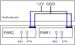
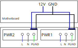
Power Supply Configuration
The S6720-30C-EI-24S-AC can be configured with a single power module or double power modules for 1+1 power redundancy. AC and DC power modules can be used together in the same switch.
Heat Dissipation
The S6720-30C-EI-24S-AC uses pluggable fan modules for forced air cooling. Air flows in from the left side, right side, and front panel, and exhausts from the rear panel.

This figure only shows the airflow direction and does not depict the actual device.
Technical Specifications
Table 4-138 lists technical specifications of the S6720-30C-EI-24S-AC.
|
Item |
Description |
|---|---|
|
Memory (RAM) |
2 GB |
|
Flash |
512 MB in total. To view the available flash memory size, run the display version command. |
|
Mean time between failures (MTBF) |
80.60 years (without card) |
|
Mean time to repair (MTTR) |
2 hours |
|
Availability |
> 0.99999 |
|
Service port surge protection |
NA |
|
Power supply surge protection |
|
|
Dimensions (H x W x D) |
|
|
Weight (with packaging) |
9.8 kg (21.61 lb) |
|
Stack ports |
|
|
RTC |
Supported |
|
RPS |
Not supported |
|
PoE |
Not supported |
|
Rated voltage range |
100 V AC to 240 V AC, 50/60 Hz -48 V DC to -60 V DC |
|
Maximum voltage range |
90 V AC to 264 V AC, 47 Hz to 63 Hz -38.4 V DC to -72 V DC |
|
Maximum power consumption (100% throughput, full speed of fans) |
233.7 W |
|
Typical power consumption (30% of traffic load, tested according to ATIS standard) |
147 W (without card) |
|
Operating temperature |
0°C to 45°C (32°F to 113°F) at an altitude of 0-1800 m (0-5906 ft.) NOTE:
When the altitude is 1800-5000 m (5906-16404 ft.), the highest operating temperature reduces by 1°C (1.8°F) every time the altitude increases by 220 m (722 ft.). |
|
Storage temperature |
-40°C to +70°C (-40°F to +158°F) |
|
Noise under normal temperature (27°C, sound power) |
< 72.1 dB(A) |
|
Relative humidity |
5% to 95%, noncondensing |
|
Operating altitude |
0-5000 m (0-16404 ft.) |
|
Certification |
|
|
Part number |
02350DMN |
Reviews
There are no reviews yet.