
S5735-S24P4X
Version Mapping
Table 4-1633 lists the mapping between the S5735-S24P4X chassis and software versions.
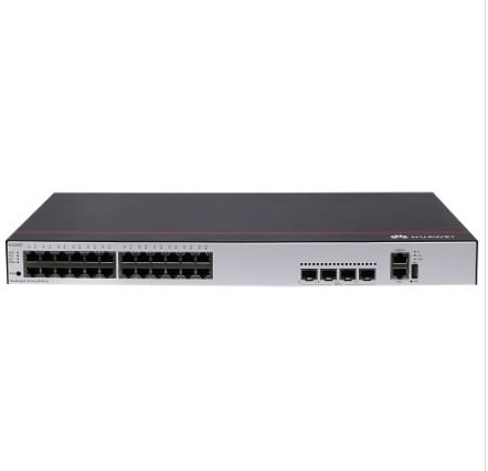
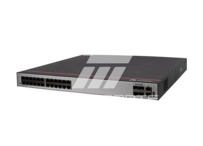
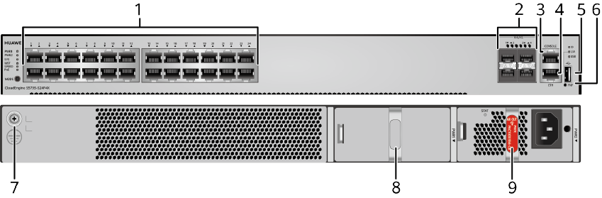
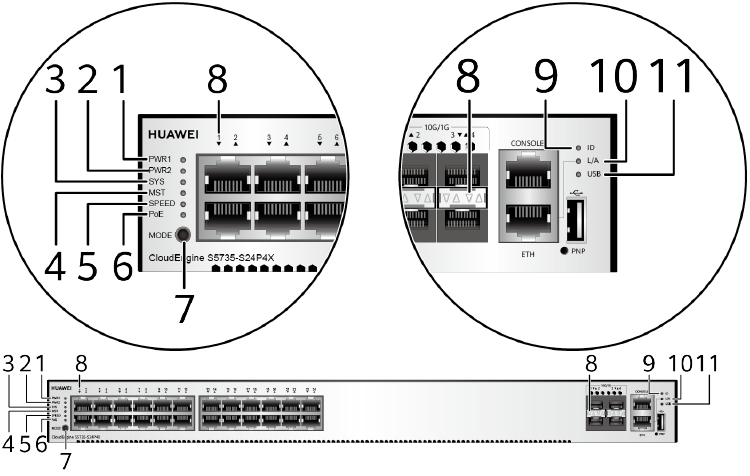
Appearance and Structure
|
1 |
Twenty-four PoE+ 10/100/1000BASE-T ports |
2 |
Four 10GE SFP+ ports Applicable modules and cables:
|
|
3 |
One console port |
4 |
One ETH management port |
|
5 |
One USB port |
6 |
One PNP button NOTICE:
To restore the factory settings and reset the switch, hold down the button for at least 6 seconds. To reset the switch, press the button. Resetting the switch will cause service interruption. Exercise caution when you press the PNP button. |
|
7 |
Ground screw NOTE:
It is used with a ground cable.
|
8 |
Power module slot 1 NOTE:
Applicable power module:
|
|
9 |
Power module slot 2 NOTE:
Applicable power module:
|
– |
– |
Port Description
10/100/1000BASE-T port
10GE SFP+ port
Console port
ETH management port
|
Attribute |
Description |
|---|---|
|
Connector type |
RJ45 |
|
Standards compliance |
IEEE802.3 |
|
Working Mode |
10/100 Mbit/s auto-sensing |
|
Maximum transmission distance |
100 m |
In V200R012C00 and later versions, you can log in to the switch that contains the ETH management port for the first time through the ETH port. For details, see “First Login to a Switch” in the Configuration Guide – Basic Configuration. If you have logged in to the switch for the first time by pressing and holding the MODE button for 6 seconds or longer and saved the configuration, the default configuration on the ETH port will be cleared. In this case, you cannot log in to the switch for the first time through the ETH port. You are advised to log in to the switch for the first time through the ETH port.
USB port

USB flash drives from different vendors differ in model compatibility and drivers. If a USB flash drive cannot be used, try to replace it with another one from a mainstream vendor. Switches support a maximum of 128 GB USB flash drives.
Indicator Description
- If the switch has no configuration file, the system attempts to enter the web initial login mode. In this mode, the status of mode indicators is as follows:
- If the system enters the web initial login mode successfully, all mode indicators turn green and stay on for a maximum of 10 minutes.
- If the system fails to enter the initial login mode, all mode indicators fast blink for 10 seconds and then restore the default status.
- If the switch has a configuration file, the system cannot enter the web initial login mode. In this case, all mode indicators fast blink for 10s, and then return to the default states.
|
No. |
Indicator |
Name |
Color |
Status |
Description |
|---|---|---|---|---|---|
|
1 |
PWR1 |
Power module indicator |
– |
Off |
No power module is available in power module slot 1, or the switch has only one power module but the power module does not work normally. |
|
Green |
Steady on |
A power module is installed in power module slot 1 and is working normally. |
|||
|
Yellow |
Steady on |
The switch has two power modules installed. Any of the following situations occurs in power module slot 1:
|
|||
|
2 |
PWR2 |
Power module indicator |
– |
Off |
No power module is available in power module slot 2, or the switch has only one power module but the power module does not work normally. |
|
Green |
Steady on |
A power module is installed in power module slot 2 and is working normally. |
|||
|
Yellow |
Steady on |
The switch has two power modules installed. Any of the following situations occurs in power module slot 2:
|
|||
|
3 |
SYS |
System status indicator |
– |
Off |
The system is not running. |
|
Green |
Fast blinking |
The system is starting. |
|||
|
Green |
Steady on |
During the system startup preparation phase, the SYS indicator is steady green, which lasts for a maximum of 30 seconds. |
|||
|
Green |
Slow blinking |
The system is running normally. |
|||
|
Red |
Steady on |
The system does not work normally after registration, or a fan alarm or a temperature alarm has been generated. |
|||
|
4 |
MST |
Stack indicator |
– |
Off |
|
|
Green |
Steady on |
The stack mode is selected. The switch is a standby or slave switch in a stack, and the service port indicators show the stack ID of the switch. |
|||
|
Green |
Blinking |
|
|||
|
5 |
SPEED |
Speed indicator |
– |
Off |
The speed mode is not selected. |
|
Green |
Steady on |
The speed mode is selected, and service port indicators show the speed of each port. |
|||
|
6 |
PoE |
PoE indicator |
– |
Off |
The PoE mode is not selected. |
|
Green |
Steady on |
The PoE mode is selected, and service port indicators show the PoE status of each port. |
|||
|
7 |
MODE |
Mode switch button |
– |
– |
If you do not press the MODE button within 45 seconds, the service port indicators restore to the default mode. In this case, the SPEED and PoE indicators are off. |
|
8 |
– |
Service port indicator |
Meanings of service port indicators vary in different modes. For details, see Table 4-1639 and Table 4-1640. |
||
|
9 |
ID |
ID indicator |
– |
Off |
The ID indicator is not used (default state). |
|
Blue |
Steady on |
The indicator identifies the switch to maintain. The ID indicator can be turned on or off remotely to help field engineers find the switch to maintain. |
|||
|
10 |
L/A |
ETH port indicator |
– |
Off |
The ETH port is not connected. |
|
Green |
Steady on |
The ETH port is connected. |
|||
|
Green |
Blinking |
The ETH port is sending or receiving data. |
|||
|
11 |
USB |
USB-based deployment indicator |
– |
Off |
|
|
Green |
Steady on |
A USB-based deployment has been completed. |
|||
|
Green |
Blinking |
The system is reading data from a USB flash drive. |
|||
|
Yellow |
Steady on |
The switch has copied all the required files and completed the file check. The USB flash drive can be removed from the switch. |
|||
|
Red |
Blinking |
An error has occurred when the system is executing the configuration file or reading data from the USB flash drive. |
|||
|
Display Mode |
Color |
Status |
Description |
|---|---|---|---|
|
Default mode |
– |
Off |
The port is not connected or has been shut down. |
|
Green |
Steady on |
A link has been established on the port. |
|
|
Green |
Blinking |
The port is sending or receiving data. |
|
|
MST stack mode |
– |
Off |
Port indicators do not show the stack ID of the switch. |
|
Green |
Steady on |
The switch is not the master switch in a stack.
|
|
|
Green |
Blinking |
The switch is the master switch in a stack.
|
|
|
Speed mode |
– |
Off |
The port is not connected or has been shut down. |
|
Green |
Steady on |
10M/100M/1000M port: The port is operating at 10 Mbit/s or 100 Mbit/s. 1000M/10GE port: The port is operating at 1000 Mbit/s. |
|
|
Green |
Blinking |
10M/100M/1000M port: The port is operating at 1000 Mbit/s. 1000M/10GE port: The port is operating at 10 Gbit/s. |
|
|
PoE mode |
– |
Off |
The port is not providing power to a powered device (PD). |
|
Green |
Steady on |
The port is providing power to a PD. |
|
|
Yellow |
Steady on |
The PoE function is disabled on the port. |
|
|
Yellow |
Blinking |
The port stops providing PoE power because of an exception (for example, an incompatible PD is connected to the port). |
|
|
Green and yellow |
Blinking green and yellow alternately |
The port fails to supply power to a PD due to one of the following reasons:
|
|
Display Mode |
Color |
Status |
Description |
|---|---|---|---|
|
Default mode |
– |
Off |
The port is not connected or has been shut down. |
|
Green |
Steady on |
A link has been established on the port. |
|
|
Yellow |
Blinking |
The port is sending or receiving data. |
|
|
MST stack mode |
– |
Off |
Port indicators do not show the stack ID of the switch. |
|
Green and yellow |
Steady on |
The switch is not the master switch in a stack.
|
|
|
Green and yellow |
Blinking |
The switch is the master switch in a stack.
|
|
|
Speed mode |
– |
Off |
The port is not connected or has been shut down. |
|
Green and yellow |
Steady on |
10M/100M/1000M port: The port is operating at 10 Mbit/s or 100 Mbit/s. 100M/1000M port: The port is operating at 100 Mbit/s. 1000M/10GE port: The port is operating at 1000 Mbit/s. |
|
|
Green and yellow |
Blinking |
10M/100M/1000M port: The port is operating at 1000 Mbit/s. 100M/1000M port: The port is operating at 1000 Mbit/s. 1000M port: The port is operating at 1000 Mbit/s. 1000M/10GE port: The port is operating at 10 Gbit/s. |
Power Supply Configuration
The switch is a PoE switch and supports two power module slots, each of which can have a 1000 W PoE or 600 W PoE power module installed. Pluggable AC and DC PoE power modules can be used together in the same switch.
|
Power Module 1 |
Power Module 2 |
Available PoE Power |
Maximum Number of Ports (Fully Loaded) |
|---|---|---|---|
|
1000 W AC (220 V) 1000 W DC |
– |
874 W |
|
|
1000 W AC (110 V) |
– |
779 W |
|
|
1000 W AC (220 V) 1000 W DC |
1000 W AC (220 V) 1000 W DC |
1600 W |
|
|
1000 W AC (110 V) 1000 W DC |
1000 W AC (110 V) |
1600 W |
|
|
600 W AC (220 V) |
– |
494 W |
|
|
600 W AC (110 V) |
– |
209 W |
|
|
600 W AC (220 V) |
600 W AC (220 V) |
1064 W |
|
|
600 W AC (110 V) |
600 W AC (110 V) |
494 W |
|
|
1000 W AC (220 V) 1000 W DC |
600 W AC (220 V) |
1444 W |
|
When a switch has two power modules installed, the two power modules work in redundancy mode to provide power for the chassis and in load balancing mode to provide power for PDs.
Heat Dissipation
The S5735-S24P4X has two built-in fans for forced air cooling. Air flows in from the left, right, and front sides, and exhausts from the rear panel.

This figure only shows the airflow direction and does not depict the actual device.
Technical Specifications
Table 4-1642 lists technical specifications of the S5735-S24P4X.
|
Item |
Description |
|---|---|
|
Memory (RAM) |
1 GB |
|
Flash |
512 MB in total. To view the available flash memory size, run the display version command. |
|
Mean time between failures (MTBF) |
59.88 years |
|
Mean time to repair (MTTR) |
2 hours |
|
Availability |
> 0.99999 |
|
Service port surge protection |
Common mode: ±7 kV |
|
Power supply surge protection |
|
|
Dimensions (H x W x D) |
|
|
Weight (with packaging) |
7.39 kg (16.29 lb) |
|
Stack ports |
Any 10/100/1000BASE-T ports or 10GE SFP+ ports (applicable in V200R019C10 and later versions) |
|
RTC |
Supported |
|
RPS |
Not supported |
|
PoE |
Supported |
|
Rated voltage range |
|
|
Maximum voltage range |
|
|
Maximum power consumption (100% throughput, full speed of fans) |
|
|
Typical power consumption (30% of traffic load)
|
51 W |
|
Operating temperature |
-5°C to +50°C (23°F to 122°F) at an altitude of 0-1800 m (0-5906 ft.)
NOTE:
When the altitude is 1800-5000 m (5906-16404 ft.), the highest operating temperature reduces by 1°C (1.8°F) every time the altitude increases by 220 m (722 ft.). The switch cannot be started when the ambient temperature is lower than 0°C (32°F). |
|
Short-term operating temperature |
-5°C to +55°C (23°F to 131°F) at an altitude of 0-1800 m (0-5906 ft.) NOTE:
When the altitude is 1800-5000 m (5906-16404 ft.), the highest operating temperature reduces by 1°C (1.8°F) every time the altitude increases by 220 m (722 ft.). The equipment can operate beyond the normal operating temperature range for a short-term period, but the following conditions must be met:
The equipment may be damaged or experience unexpected exceptions if any of the preceding limits is exceeded. The equipment cannot start when the temperature is lower than 0°C (32°F). The maximum distance of optical modules used in these conditions cannot exceed 10 km. |
|
Storage temperature |
-40°C to +70°C (-40°F to +158°F) |
|
Noise under normal temperature (27°C, sound power) |
< 58.9 dB(A) |
|
Relative humidity |
5% to 95%, noncondensing |
|
Operating altitude |
0-5000 m (0-16404 ft.) |
|
Certification |
|
|
Part number |
98010940 |
Reviews
There are no reviews yet.